de
de fr
fr es
es pt
pt it
it ru
ru
- Ultrasonic Fabric Welding Machine
- Ultrasonic Sieving System
- Ultrasonic Plastic Welding Machine
- Ultrasonic Cutting Machine
- Ultrasonic Welding System
- Ultrasonic Metal Welding Machine
- More >>

- Core ProductsThe core products of Jiayuanda mainly include ultrasonic plastic welding machine, ultrasonic metal welding machine, ultrasonic non-woven equipment, ultrasonic cutting equipment and ultrasonic welding system, which are widely used in various industries and can realize welding, cutting, lamination, joining, sealing, etc. Craft.
- More >>

- Ultrasonic Lace MachineJiayuanda Technology ultrasonic lace machine has the advantages of adjustable power, efficient slitting, multiple protection, silence and so on. It is suitable for making: lace dress, ribbon, decorative products, handkerchief, tablecloth, curtain, bedspread, pillow case, quilt cover, tent, disposable operating clothes, non-woven shopping bags, non-woven fabrics and other supplies.Applicable material: chemical fiber cloth, artificial leather, non - woven cloth, spray cotton, thermoplastic film, chemical plastic sheet, etc.
- More >>

- Ultrasonic Sieving SystemMAR series is a professional ultrasonic screening system, which is composed of ultrasonic generator and screen transducer. It can meet the use range of 28 ~ 38kHz frequency. The system can automatically track the best resonant frequency and compensate for the detuning caused by heating and other reasons; It can also be added to any new or existing vibrating screen
- More >>

- Ultrasonic Plastic Welding MachineJiayuanda Technology original brands ultrasonic plastic welding machine;
basic version H40/H40S;precision version H60/H60S;high precision version H80/H80S;it can meet the requirements of complex welding working environment on site.Ultrasonic Welding Machine is an ultrasonic welder designed for welding various plastics (PVC, PP, PE, ABS, etc.) and fabrics (Polyester, nonwoven fabric, etc.). It is widely used in welding plastic products, including led lampshade, chargers, reflectors,...
- More >>

- Meet Various Cutting RequirementsJiayuanda Technology ultrasonic cutting machine can be used to cut food, plastics, rubber, cloth, etc., with automatic frequency tracking ultrasonic generator, the cut effect is fine and smooth, doesn't stick to the knife, the speed is fast, and the cutting knife has a variety of sizes.
- More >>

- Professional Custom Ultrasonic SolutionsUltrasonic welding system is composed of ultrasonic generator, ultrasonic transducer and ultrasonic application tool head, which is widely used in mask making, food cutting, biological extraction homogenization, rubber cutting, paper cup welding, zipper welding and cutting and non-woven fabric welding and cutting industries.According to the different application requirements of customers to provide a complete ultrasonic solutions.
- More >>
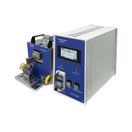
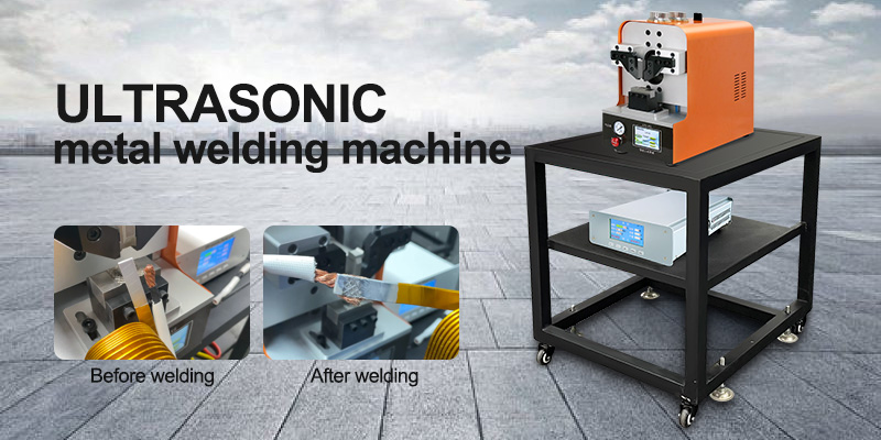
- Ultrasonic Metal Welding MachineUltrasonic metal welding machines are widely used in electronics, electrical appliances, batteries, automobiles and other industries. Ultrasonic output power is stable, fast, good welding quality, high efficiency and energy saving, suitable for manual or supporting automation equipment applications.
- More >>

- Ultrasonic industry applicationUltrasonic welding technology can realize the welding, cutting, punching, embossing, lamination, sealing and other functions of plastic, metal, rubber, non-woven fabrics and other materials. It is used in automobiles, food, health, medical, electronics, consumer
- More >>

- Automotive industry applicationsUltrasonic is very suitable for welding a large number of automotive parts, such as interior parts and exterior parts made of thermoplastic materials, engine room parts, and non-ferrous metal parts for cable harnesses and lithium-ion batteries. Jiayuanda's ultrasonic welding technology is for these The complex process requirements provide a quick and economical solution and guarantee the highest welding quality.
● Good sealing
● High firmness
● Precise size
● The appearance is flawless
- More >>

- Packaging industry applicationsIn order to better protect food, retain its nutrients and good taste, a good packaging is particularly important. Ultrasonic sealing and welding technology provides the production possibility for packaging materials that use thermoplastic coatings, such as shells, tea bags, spouts, Valves, film packaging, beverage packaging, blister trays, etc., can all use Jiayuanda's superb ultrasonic welding technology, with tight welding seams, high speed production, and economical and practical.
- More >>

- Hygiene products industry applicationsWhen manufacturing hygiene products such as adult hygiene products, baby hygiene products, women's hygiene products, cosmetics and skin care products, there are high requirements for craftsmanship, requiring continuity, high speed, precision, economy, the shortest equipment time, and the most abrasion. Lightweight and stable product quality, these requirements cannot be met by conventional traditional connection technology. The ultrasonic welding technology developed by Jiayuanda combines these advantages and is very popular in the market.
● Laminated soft, super comfortable to wear
● Uniform melting point, strong multilayer composite
● Tight welding to achieve comprehensive protection
● No glue connection to meet skin-friendly needs
● Can still maintain elasticity after welding
- More >>

- Medical Technology Industry ApplicationsUltrasonic welding technology is widely used in medical components, medical packaging, medical and health products and wound healing materials, etc., without damaging the workpiece, the welding is strong and soft, the sealing is good, and the size is accurate.
- More >>

- Textile industry applicationsTextile Industry Application Ultrasonic technology does not need to use needle and thread accessories, can complete stitching, edge cutting, pressing, carving, opening, forming and other processes, can meet the welding / cutting requirements of different materials / thickness, replace the traditional welding / bonding process. Suitable for making: nonwoven bag, carbon bag, tea bag, masks, lace clothes, ribbon, curtains, pillowcases, quilt covers, tents, nonwoven cloth, etc. ; Suitable materials: non - woven fabric, chemical fiber fabric, artificial leather, glue spray cotton, thermoplastic film, chemical plastic film, etc.
- More >>

- Consumer goods industry applicationsThe application of ultrasonic welding technology to daily consumer goods can not only reduce costs, but also achieve exquisite appearance, accurate size, good sealing, and no indentation on the surface, which can meet the high requirements of different geometric shapes.
- More >>

- Automation industry applicationsIn the field of automation industry, the automation equipment itself is more complex, and the market demand for efficient automation equipment is increasing. Jiayuanda provides a good solution in the ultrasonic system. Either as a welding system integrated into automation equipment, or as a single component integrated into a special welding machine.
- More >>

- R&D team researchWith fast delivery capabilities, strict quality control management, product research and development and continuous updates, it has won praise from customers. An ultrasonic laboratory is also specially set up, and the project evaluation, design, optimization, testing and other links can be carried out in the laboratory, and the solution is tailored for you.
- More >>

- Ultrasound Research InstituteYou can bring your own samples, prototypes, and sketches to our ultrasonic laboratory. Our engineers and technicians can provide you with evaluation, design, optimization, testing and other services according to your special requirements.
- More >>

- Fast Delivery CapabilityThe industrial park-style production plant covers an area of 6000m²+, with a modern production team of 80+ people, which provides a strong guarantee for rapid delivery.
- More >>

- Strict Quality ControlComplete quality management system, with a professional incoming inspection team and process quality control team, products have passed a series of professional certifications such as EU certification, FCC certification, ROHS certification, and TEST certification to ensure product quality.
- More >>

- R&D Team ResearchThe core team of product research and development has 15+ people, covering the fields of electronics, software, machinery, electrical, structure, etc., strive for perfection and keep making progress.
- More >>

- Insight into the industry, all dynamics in itAlways provide you with ultrasonic industry information, hot news, special reports, and ultrasonic equipment maintenance and maintenance.
- More >>

- Provide you with industry trendsAlways provide you with ultrasonic industry information, hot news, special reports, and ultrasonic equipment maintenance and maintenance.
- More >>

- Jiayuanda Exhibition Activity ReportJiayuanda provides you with exhibition reports on ultrasound-related industries, so that you know everything about ultrasound.
- More >>

- Brand manufacturer, strongJiayuanda Technology Co., Ltd. is a leading ultrasonic technology development national high-tech enterprise, the main products are ultrasonic plastic welding machine, ultrasonic metal welding machine, ultrasonic lace machine, ultrasonic cutting equipment, ultrasonic welding system, ultrasonic generator and changer Core accessories such as energy sensors can develop ultrasonic products in different application fields according to customer needs
- More >>

- Brand Manufacturer, StrongJiayuanda technology is a national high-tech enterprise focusing on the development of ultrasonic technology. The main products are ultrasonic generator, ultrasonic transducer, ultrasonic application tool head and ultrasonic application equipment, which are mainly used in ultrasonic cleaning, welding, atomization, extraction and cutting. They are suitable for medical, textile, plastic, metal, food, packaging, semiconductor and other industries. The products are sold all over the world and are widely praised by customers.
- More >>

- Clang Forward, FruitfulFrom the beginning of its establishment, Jiayuanda has gradually developed and grown by a small team of several people. Now it is an advanced enterprise in the field of ultrasound. Now the team has more than one hundred people, and the plant area is more than 6,000 square meters.
- Work with you for a win-win situationJiayuanda Technology takes customers as the center and creates value for customers; strives to create a competitive team; continuously enhances competitiveness!